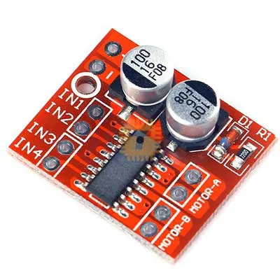
DRV8833 Dual DC H-Bridge Speed Controller Motor Driver Module Price in Sri Lanka

Tronic.lkListing · checkedChecked 10 Nov 2026
Rs200In stock
Go to Tronic.lk ↗https://tronic.lk/product/drv8833-dual-dc-h-bridge-speed-controller-motor-driver-Call0777854444WhatsApp+94764485607
Search for it on
Price history
Price at Tronic.lk at the end of each day · last 90 daysNo price history yetWe started tracking this listing recently. The chart and change tables appear after the first price or stock change.
Price insights
- Today at Tronic.lk
- Rs200
Description
The DRV8833 Dual DC H-Bridge Speed Controller Motor Driver Module is an ultra-compact, high-efficiency dual MOSFET H-bridge driver board engineered for low-voltage battery-powered robotics, micro-actuator control, and dual-phase bipolar stepper motor driving. Based on the Texas Instruments DRV8833 integrated circuit, it replaces legacy, power-wasting BJT-based drivers (like the L298N and L293D) by utilizing low-resistance N-channel power MOSFET H-bridges (RDS(on) ≈ 360 mΩ combined). Operating down to 2.7V, it delivers continuous drive currents up to 1.5A per bridge without requiring bulky heat sinks, while incorporating cycle-by-cycle current limiting, low-power sleep mode, and comprehensive thermal and short-circuit protections.
Specifications
- Driver IC: Texas Instruments DRV8833 Dual H-Bridge Motor Driver
- Output Channels: 2 Independent DC Motor H-Bridges (or 1 × 4-wire Bipolar Stepper Motor)
- Motor Power Supply Range (VM / VCC): 2.7 V DC to 10.8 V DC (Optimized for 1S/2S Li-ion, 4×AA, or 5V–9V rails)
- Logic Interface Voltage Range (IN1–IN4 / ULT): 2.7 V to 5.5 V DC (Directly compatible with 3.3V and 5V logic without level shifting)
- Continuous Output Current: Up to 1.5 A per channel (at 25°C with proper PCB ground planes)
- Peak / Surge Output Current: Up to 2.0 A per channel (Intermittent pulse tolerance < 500>
- Parallel Channel Mode (Single DC Motor): Bridges can be tied in parallel to deliver up to 3.0 A continuous (4.0 A peak)
- H-Bridge On-Resistance: Low RDS(on) of ≈ 360 mΩ typical (High-side + Low-side combined per H-bridge)
- Control Method: Dual-pin Direction + High-Frequency PWM speed modulation (Up to 50 kHz switching frequency)
- Operating Modes: Forward, Reverse, Coast / Free-running (High-Z), and Active Dynamic Electronic Braking
- Sleep Mode Quiescent Current: ≤ 1.6 μA (When ULT / SLEEP pin is pulled LOW)
- Built-in Protections:
- Internal Overcurrent Protection (OCP) with fault conditions
- Under-Voltage Lockout (UVLO) around 2.4V
- Thermal Shutdown (TSD) with automatic recovery (≥ 160°C)
- Internal cross-conduction (shoot-through) prevention circuitry
- Form Factor: Compact Breakout PCB (18.5 mm × 16.0 mm footprint)
- Pin Pitch: Standard 2.54 mm (0.1") breadboard-friendly pitch
- Operating Temperature Envelope: -40°C to +85°C
- Net Weight: Approx. 1.5 g to 2.0 g
Features
- Ultra-Low Voltage Drop (High Efficiency): Employs modern low-RDS(on) DMOS power switches that waste virtually no energy compared to traditional L298N drivers (which lose 1.5V–2.5V in heat), making it ideal for maximizing battery life on 3.7V / 7.4V lithium-powered platforms.
- Native 3.3V & 5V Logic Compatibility: Input threshold levels accept standard 3.3V logic directly from ESP32, STM32, and Raspberry Pi Pico, as well as 5V logic from classic Arduino boards without level shifters.
- Active Fast Dynamic Braking: Pulling both directional control pins HIGH (or applying complementary PWM) shorts the motor terminals through the lower MOSFETs, braking the motor instantly without coasting.
- Ultra-Low Quiescent Sleep Mode: Bringing the dedicated sleep pin (ULT / SLEEP) low disables the internal charge pump and gate drivers, dropping standby current below 2 μA to prevent battery drain during inactive states.
- Parallelable H-Bridge Design: Bridge outputs and input control pins can be paralleled into a single, high-current output channel (up to 3A continuous) to drive larger single DC coreless or geared motors.
Common Applications
- Miniature Mobile Robotics: Driving differential N20 micro-metal gearmotors on line-following, maze-solving, and mini-sumo robotics platforms.
- Bipolar Stepper Actuation: Stepping 4-wire micro-stepper motors (such as those in optical CD/DVD drive carriages and miniature linear slides).
- Battery-Powered Toy & RC Conversions: Upgrading small RC vehicles, robotic grippers, and motorized camera pan/tilt mechanisms.
- Haptic & Vibration Actuators: Precision bi-directional drive of linear resonant actuators (LRA) and eccentric rotating mass (ERM) motors.
- Solenoid & Valve Driving: Actuating bi-directional latching solenoid valves and mechanical locking pins.
Usage Tips & Pinout Configuration
- Pin Assignment & Hook-Up:
- VM: Motor Power Input (2.7V to 10.8V DC). Connect directly to your battery pack or motor power source.
- GND: Common Ground. Must be tied to both the motor battery negative and your microcontroller ground.
- IN1 / IN2: Logic inputs for Motor Channel A (OUT1 / OUT2).
- IN3 / IN4: Logic inputs for Motor Channel B (OUT3 / OUT4).
- ULT (Sleep Pin): Module Sleep control. Must be pulled HIGH (to 3.3V or 5V) to enable the driver. If left floating on breakout boards lacking a pull-up resistor, the chip stays in low-power sleep and will not output voltage.
- EEP / FAULT (if broken out): Open-drain fault indicator. Pulls LOW during thermal shutdown, undervoltage, or overcurrent events.
- Control Logic Truth Table (Motor A Example):
- IN1 = HIGH, IN2 = LOW → Forward Rotation.
- IN1 = LOW, IN2 = HIGH → Reverse Rotation.
- IN1 = HIGH, IN2 = HIGH → Brake (Motor terminals tied to ground, immediate deceleration).
- → Coast (High-impedance, motor free-wheels to a stop).
- Speed Modulation: Apply a PWM signal (1 kHz to 20 kHz) to one pin while holding the opposite pin LOW (or apply inverted PWM for active braking drive).
- Decoupling & Motor Noise Suppression:
- Always place a 100 μF to 220 μF electrolytic capacitor across the VM and GND lines close to the module to absorb inductive inductive kickback voltage spikes.
- Solder a 0.1 μF (104) ceramic capacitor directly across each DC motor's terminals to suppress high-frequency brush arcing that can trigger spurious microcontroller resets.
- Current Limit Resistor Tuning (Isense):
- Breakout boards usually come with pre-soldered surface-mount zero-ohm jumpers or 0.2Ω resistors at the current-sense pins (AISEN / BISEN)
Questions
About this listing at Tronic.lkWhat is the price of DRV8833 Dual DC H-Bridge Speed Controller Motor Driver Module at Tronic.lk in Sri Lanka?
Rs 200, checked 10 Nov 2026.
Is DRV8833 Dual DC H-Bridge Speed Controller Motor Driver Module in stock at Tronic.lk in Sri Lanka?
Yes, it was in stock at Tronic.lk at the last check.
Where can I buy DRV8833 Dual DC H-Bridge Speed Controller Motor Driver Module in Sri Lanka?
Tronic.lk sells it on tronic.lk. You can also call or WhatsApp the shop during opening hours.
Rs200at Tronic.lk · In stock
Go to Tronic.lk ↗https://tronic.lk/product/drv8833-dual-dc-h-bridge-speed-controller-motor-driver-