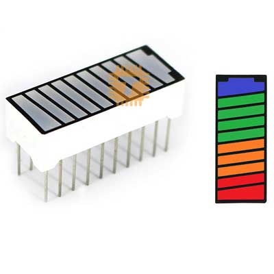
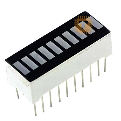
LED Bar Graph Display Green 10 Segment Ultra Bright KYX-B10G
Price in Sri Lanka
Seven SegmentDisplays
Tronic.lk

Rs 120
In stock
Updated 01 Nov 2026
Opening hours
Closed now
- Monday09:00 - 19:00
- Tuesday09:00 - 19:00
- Wednesday09:00 - 19:00
- Thursday09:00 - 19:00
- Friday09:00 - 19:00
- Saturday09:00 - 19:00
- SundayToday09:00 - 19:00
Search for it on
Description
The KYX-B10G is an ultra-bright, 10-segment monochromatic green LED bar graph display packaged in a standard 20-pin dual in-line package (DIP). Designed for instrumentation, process monitoring, and audio visualization, each bar houses an individual high-efficiency green LED element under a white diffused window set into a black faceplate. The display delivers high-contrast, uniform illumination suitable for ambient or direct viewing across consumer, automotive, and industrial user interfaces.
Specifications
- Model: KYX-B10G
- Display Type: 10-Segment LED Bar Graph
- Emitted Colour: Ultra Bright Green
- Peak Wavelength: ~565nm to 572nm (Standard Green)
- Package Style: 20-Pin Dual In-line Package (DIP-20)
- Pin Pitch: 2.54 mm (Standard breadboard and perfboard spacing)
- Row Spacing: 7.62 mm (0.3 inches standard DIP width)
- Forward Current per Segment: 15mA to 20mA (Nominal), 30mA (Peak absolute max)
- Forward Voltage Drop (Vf): 2.1V to 2.4V per segment (Typical 2.2V at 20mA)
- Reverse Voltage Max (Vr): 5V
- Luminous Intensity: 70 mcd to 120 mcd per segment
- Operating Temperature: -25°C to +85°C
- Face / Segment Finish: Black faceplate with milky white diffused segment windows
Interface and Pinout Guide
Each of the 10 segments is electrically independent, with dedicated anode and cathode leads routed to opposing pins across the 20-pin DIP layout:
- Segment 1: Pin 1 to Pin 20
- Segment 2: Pin 2 to Pin 19
- Segment 3: Pin 3 to Pin 18
- Segment 4: Pin 4 to Pin 17
- Segment 5: Pin 5 to Pin 16
- Segment 6: Pin 6 to Pin 15
- Segment 7: Pin 7 to Pin 14
- Segment 8: Pin 8 to Pin 13
- Segment 9: Pin 9 to Pin 12
- Segment 10: Pin 10 to Pin 11
(Note: Because the segments have no internal shared common bus, the module can be configured in external Common Anode, Common Cathode, or multiplexed arrangements depending on your circuit wiring).
Key Features
- High-Efficiency Green Output: Emits crisp, vibrant green illumination with even diffusion across all active segments, eliminating dark spots and light bleed.
- Fully Isolated LED Channels: Independent pin pairs for every segment give designers complete freedom to implement high-side driving, low-side sinking, or matrix scanning.
- Standard DIP-20 Layout: Directly compatible with solderless breadboards, perfboards, automated PCB pick-and-place lines, and 20-pin IC sockets.
- Broad Driver IC Support: Works seamlessly with classic analog display drivers (LM3914, LM3915, LM3916), shift registers (74HC595, CD4094, TPIC6B595), and direct microcontroller GPIO arrays.
Common Applications
- Industrial Control & Automation: Monitoring valve positions, tank fluid levels, conveyor speeds, and operating temperatures.
- Battery & Power Systems: State-of-charge (SoC) gauges, solar charging activity, and DC bus voltage indicators.
- Audio Engineering: VU level meters, peak limiters, equalizer band displays, and dynamic signal strength monitors.
- Embedded Development & Prototyping: Visual status bars and progress indicators for Arduino, ESP32, STM32, and Raspberry Pi projects.
Usage Tips
- Current Limiting Resistors: Always include a current-limiting resistor on each segment line. For a 5V supply rail with a typical 2.2V forward drop at 15mA, use a series resistor between 180Ω and 220Ω per segment.
- Total Current Sourcing / Sinking: Illuminating all 10 segments simultaneously at 15mA draws roughly 150mA total. Verify that your host microcontroller GPIO port or driver chip does not exceed its maximum aggregate current limit; use an external shift register or transistor array if required.
- Polarity Identification: Before soldering, check segment polarity using a multimeter set to diode-test mode across opposing pins (such as Pin 1 and Pin 20) to confirm your intended anode and cathode layout.
Frequently asked questions
What is the price of LED Bar Graph Display Green 10 Segment Ultra Bright KYX-B10G in Sri Lanka?▾
The current price of LED Bar Graph Display Green 10 Segment Ultra Bright KYX-B10G in Sri Lanka is Rs 120 at Tronic.lk.
Is LED Bar Graph Display Green 10 Segment Ultra Bright KYX-B10G available in Sri Lanka?▾
Yes, LED Bar Graph Display Green 10 Segment Ultra Bright KYX-B10G is currently in stock at Tronic.lk in Sri Lanka.
Where can I buy LED Bar Graph Display Green 10 Segment Ultra Bright KYX-B10G in Sri Lanka?▾
You can buy LED Bar Graph Display Green 10 Segment Ultra Bright KYX-B10G in Sri Lanka at Tronic.lk. Visit 37left.lk to compare prices across multiple shops and find the best deal.
Loading...