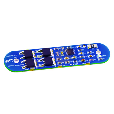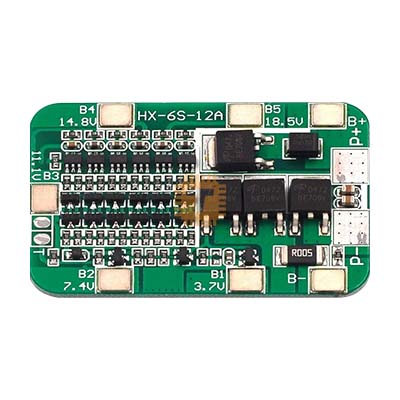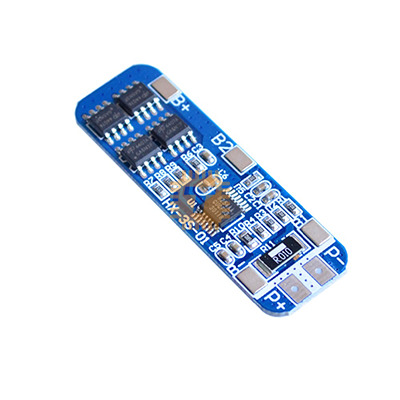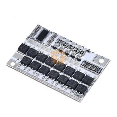
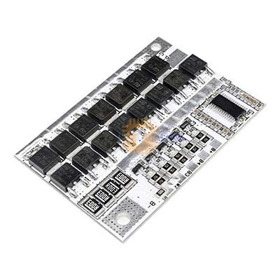
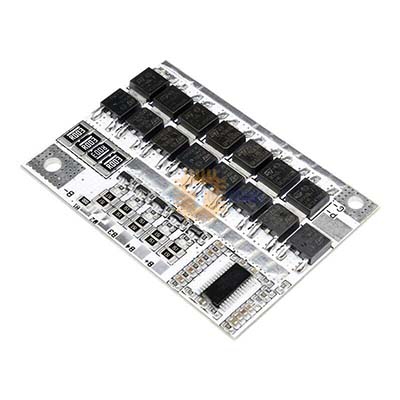
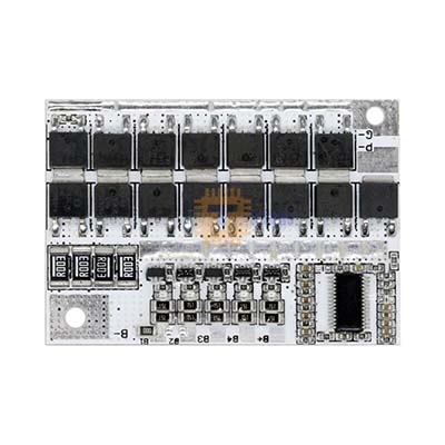
LiFePO4 4S 14.4V 100A BMS Battery Protection Board
Price in Sri Lanka
Battery Chargers & Power BanksBatteries and Chargers
Tronic.lk

Rs 850
In stock
Updated 01 Nov 2026
Opening hours
Open now
- Monday09:00 - 19:00
- Tuesday09:00 - 19:00
- Wednesday09:00 - 19:00
- Thursday09:00 - 19:00
- Friday09:00 - 19:00
- Saturday09:00 - 19:00
- SundayToday09:00 - 19:00
Search for it on
Description
The LiFePO4 4S 14.4V 100A BMS Battery Protection Board is a heavy-duty battery management system designed for 4-series Lithium Iron Phosphate (LiFePO4) battery packs. Built with high-current MOSFETs, integrated passive balancing circuitry, and onboard thermal monitoring, it provides comprehensive hardware-level protection against overcharge, deep over-discharge, short-circuit, and overcurrent conditions. It is engineered to maintain cell balance, extend battery cycle life, and ensure safe operation in solar energy storage, inverter systems, electric vehicles, and high-demand 12V/14.4V power banks.
Specifications
- Battery Chemistry: Lithium Iron Phosphate (LiFePO4) only
- Cell Configuration: 4S (4 cells in series)
- Nominal Pack Voltage: 12.8V (3.2V per cell)
- Full Charge Voltage: 14.4V to 14.6V (3.6V to 3.65V per cell)
- Continuous Discharge Current:
- Separate Port Configuration: Up to 80A
- Same Port (Common Port) Configuration: Up to 60A
- Continuous Charging Current: Up to 60A
- Peak / Overcurrent Protection: 100A (Overcharge and Over-discharge current threshold)
- Over-Discharge Current Protection Delay: 0.5 to 1.5 seconds
- Overcharge Protection (Per Cell):
- Trigger Voltage: 3.61V to 3.69V
- Protection Delay: 1.5 to 2.5 seconds
- Release / Recovery Voltage: 3.50V to 3.60V
- Over-Discharge Protection (Per Cell):
- Trigger Voltage: 2.27V to 2.43V
- Release / Recovery Voltage: 2.45V to 2.65V
- Cell Balancing:
- Balance Activation Threshold: 3.355V to 3.455V per cell
- Balance Current: ~50mA passive bleed current
- Short-Circuit Protection:
- Trigger Delay: 100 to 600 microseconds
- Recovery Condition: Cut load / disconnect load to auto-recover
- Temperature Protection: Integrated NTC temperature sensor interface
- Wire Break / Disconnection Protection: Supported (Automatic shutdown if a balance sense lead disconnects)
Terminal and Wiring Guide
- High-Current Power Solder Pads:
- B-: Connects to the main negative terminal of the 4S battery pack.
- P-: Load negative output (for common port setups) or discharge negative terminal.
- C-: Charge negative terminal (for separate port charging configurations).
- Multi-Pin Balance Sensing Harness (5-Pin Connector):
- B- (Black): Connect to Cell 1 Negative (Main Battery Pack Ground).
- B1 (White / First Sense Wire): Connect to junction between Cell 1 Positive and Cell 2 Negative (+3.2V nominal).
- B2 (White / Second Sense Wire): Connect to junction between Cell 2 Positive and Cell 3 Negative (+6.4V nominal).
- B3 (White / Third Sense Wire): Connect to junction between Cell 3 Positive and Cell 4 Negative (+9.6V nominal).
- B+ (Red / Fourth Sense Wire): Connect to Cell 4 Positive (Main Battery Pack Positive, +12.8V nominal).
- NTC Interface: Connects an external NTC thermistor probe placed between cells to guard against over-temperature conditions.
Key Features
- Comprehensive Battery Protection: Independent hardware IC protects against cell-level overcharging, deep discharge, high-current short circuits, and cell sense wire disconnection.
- Passive Cell Balancing: Onboard 50mA shunt resistors bleed excess charge from higher-voltage cells once they surpass 3.355V–3.455V, ensuring all four cells top out evenly.
- Rapid Short-Circuit Response: Shuts down output within 100 to 600 microseconds during a short-circuit event, automatically resetting once the fault load is disconnected.
- High Heat Dissipation: Features an aluminium heat spreader over the low-resistance power MOSFET bank to manage heat under sustained discharge loads.
- Flexible Port Routing: Supports both separate-port (higher discharge rating) and common-port wiring topologies depending on system requirements.
Common Applications
- 12V Lead-Acid Replacement: Upgrading SLA/AGM batteries to 12.8V LiFePO4 in UPS backups, recreational vehicles (RVs), marine boats, and trolling motors.
- Off-Grid Solar Energy Storage: Managing 12V 50Ah to 200Ah residential solar battery banks with dedicated MPPT or PWM charge controllers.
- High-Power Portable Power Stations: Driving DC-to-AC power inverters, portable camping power boxes, and high-intensity field equipment.
- Automotive Audio & Auxiliary Power: Providing high burst current for auxiliary automotive sound amplifiers and mobile lighting rigs.
Installation and Wiring Sequence
- Cell Matching: Verify that all four LiFePO4 cells are top-balanced and matched in voltage (within 0.05V of each other) and internal resistance before assembling the pack.
- Wire Main Negative: Solder a thick high-gauge wire (8 AWG to 10 AWG) from the pack's main negative terminal to the B- pad on the BMS board.
- Assemble the Balance Harness: Wire the balance harness leads starting from B- up to B+ across the cell terminals. Do not plug the balance harness into the BMS yet.
- Harness Voltage Verification: Use a digital multimeter to measure voltages between adjacent pins on the unplugged connector:
- Pin 1 (B-) to Pin 2 (B1): ~3.2V to 3.6V
- Pin 2 (B1) to Pin 3 (B2): ~3.2V to 3.6V
- Pin 3 (B2) to Pin 4 (B3): ~3.2V to 3.6V
- Pin 4 (B3) to Pin 5 (B+): ~3.2V to 3.6V
- Connect Harness: Plug the verified balance connector firmly into the BMS socket.
- Connect Output Lines: Solder the load and charge negative leads to P- and/or C-. The main positive load terminal connects directly to the pack's main B+ terminal.
Usage Tips
- Strict Chemistry Compatibility: This BMS is specifically calibrated for LiFePO4 (3.2V nominal, 3.65V peak). Do not use this board with standard Li-ion or LiPo cells (3.7V nominal, 4.2V peak), as the lower cut-off thresholds will cause severe undercharging and cell imbalance.
- Cable Sizing: When drawing continuous currents above 40A, use short, heavy-gauge multi-strand silicone wiring (8 AWG to 10 AWG) soldered with adequate heat to avoid cold joints and resistive heating.
- Initial Activation: If there is no voltage reading across B+ and P- after assembly, connect a 14.4V–14.6V LiFePO4 battery charger across B+ and P- (or C-) for 2 to 3 seconds to release the BMS sleep/protection lockout.
Frequently asked questions
What is the price of LiFePO4 4S 14.4V 100A BMS Battery Protection Board in Sri Lanka?▾
The current price of LiFePO4 4S 14.4V 100A BMS Battery Protection Board in Sri Lanka is Rs 850 at Tronic.lk.
Is LiFePO4 4S 14.4V 100A BMS Battery Protection Board available in Sri Lanka?▾
Yes, LiFePO4 4S 14.4V 100A BMS Battery Protection Board is currently in stock at Tronic.lk in Sri Lanka.
Where can I buy LiFePO4 4S 14.4V 100A BMS Battery Protection Board in Sri Lanka?▾
You can buy LiFePO4 4S 14.4V 100A BMS Battery Protection Board in Sri Lanka at Tronic.lk. Visit 37left.lk to compare prices across multiple shops and find the best deal.
Loading...