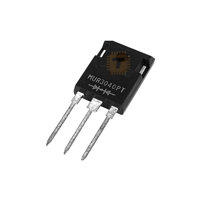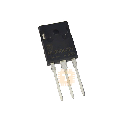
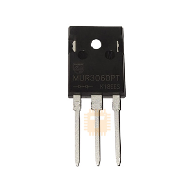
Original MUR3060PT Ultra-Fast Recovery Diode TO-247
Price in Sri Lanka
FETTransistors and Diodes
Tronic.lk

Rs 240
In stock
Updated 01 Nov 2026
Opening hours
Closed now
- Monday09:00 - 19:00
- Tuesday09:00 - 19:00
- Wednesday09:00 - 19:00
- Thursday09:00 - 19:00
- Friday09:00 - 19:00
- Saturday09:00 - 19:00
- SundayToday09:00 - 19:00
Search for it on
Description
The MUR3060PT is a dual-chip, center-tap ultra-fast recovery power rectifier diode housed in a heavy-duty TO-247 (TO-218 / TO-3P compatible) through-hole package. Engineered specifically for high-voltage, high-frequency switch-mode power conversion, the MUR3060PT features a repetitive peak reverse voltage rating of 600V, a total continuous forward current capacity of 30A (15A per diode leg), low forward voltage drop, and an ultra-fast reverse recovery time (trr) of 60ns. It is widely used in high-efficiency switch-mode power supplies (SMPS), solar inverters, high-power DC-DC converters, motor drive freewheeling circuits, and industrial battery charging systems.
Specifications
- Brand / Manufacturer: ON Semiconductor / Vishay / Industry Standard
- Part Number / Marking: MUR3060PT / U3060PT
- Diode Configuration: Dual Common Cathode (Center Tap)
- Maximum Repetitive Peak Reverse Voltage (VRRM): 600V
- Working Peak Reverse Voltage (VRWM): 600V
- Maximum DC Blocking Voltage (VR): 600V
- Average Rectified Forward Current (IF(AV)): 30A Total (15A per Diode Leg at TC = 145°C)
- Non-Repetitive Peak Forward Surge Current (IFSM): 150A (8.3ms half sine-wave per leg)
- Peak Repetitive Forward Current (IFRM): 30A per leg (Rated VR, Square Wave, 20kHz at TC = 145°C)
- Maximum Instantaneous Forward Voltage (VF): 1.5V (at IF = 15A, TC = 25°C) / 1.2V (at IF = 15A, TC = 150°C)
- Maximum Reverse Recovery Time (trr): 60ns (at IF = 1.0A, di/dt = 50A/µs)
- Maximum Reverse Leakage Current (IR): 10µA @ TJ = 25°C / 1.0mA @ TJ = 150°C
- Operating Junction & Storage Temperature Range: -65°C to +175°C
- Thermal Resistance, Junction-to-Case (RθJC): 1.5°C/W per diode leg
- Package / Case: TO-247 / SOT-93 (TO-218AC) (Pin 1: Anode 1, Pin 2: Common Cathode / Tab, Pin 3: Anode 2)
Features
- Ultra-Fast 60ns Recovery Time: Substantially reduces diode reverse-recovery switching losses, minimizing EMI emissions and increasing converter efficiency at high frequencies.
- High 600V Reverse Blocking Voltage: Provides ample safety headroom against high-voltage ringing transients in off-line power supplies and solar inverters.
- Dual Center-Tap Configuration: Integrates two matched 15A diodes with a common cathode connection to simplify full-wave secondary rectification circuits and reduce PCB component count.
- High Operating Junction Temperature (175°C): Delivers exceptional thermal headroom, ensuring long-term reliability in high-temperature industrial environments.
- Glass Passivated High-Temperature Junction: Ensures minimal reverse leakage and robust avalanche withstand capability over prolonged operational lifespans.
- Heavy-Duty TO-247 Package: Large copper mounting tab provides direct heatsink mounting for superior thermal management under heavy continuous current loads.
Common Applications
- High-Voltage SMPS Secondary Rectification: Secondary output rectification in server power units, telecom rectifiers, and high-wattage industrial power supplies.
- Solar Inverters & UPS Systems: High-frequency secondary rectification and energy recycling stages in renewable power systems and battery backup units.
- High-Power DC-DC Converters: Catch and freewheeling diode stages in industrial buck, boost, and bridge topologies.
- Industrial Battery Chargers: Fast AC-DC rectification stages for electric vehicle (EV) charging stations and high-current industrial battery packs.
- Motor Drives & Inductive Clamping: High-speed freewheeling protection across inductive motors, large solenoids, and magnetic actuators.
Usage Tips
- Heatsink Installation: Always fasten the TO-247 package securely to an adequately sized aluminum heatsink using thermal paste. Use a silicone/mica insulation sheet and shoulder washer if the heatsink must remain electrically isolated from the center Cathode.
- Single 30A Diode Configuration: To utilize the full 30A continuous rating in a single-ended output circuit, connect Pin 1 (Anode 1) and Pin 3 (Anode 2) together in parallel on the PCB.
- RC Snubber Protection: Place a small RC snubber network across each diode leg to absorb high-frequency voltage spikes and ringing caused by transformer leakage inductance.
- PCB Trace Optimization: Keep high-current loops between the transformer secondary, the diode terminals, and the output filter capacitors short and wide to minimize parasitic inductance and EMI noise.
Frequently asked questions
What is the price of Original MUR3060PT Ultra-Fast Recovery Diode TO-247 in Sri Lanka?▾
The current price of Original MUR3060PT Ultra-Fast Recovery Diode TO-247 in Sri Lanka is Rs 240 at Tronic.lk.
Is Original MUR3060PT Ultra-Fast Recovery Diode TO-247 available in Sri Lanka?▾
Yes, Original MUR3060PT Ultra-Fast Recovery Diode TO-247 is currently in stock at Tronic.lk in Sri Lanka.
Where can I buy Original MUR3060PT Ultra-Fast Recovery Diode TO-247 in Sri Lanka?▾
You can buy Original MUR3060PT Ultra-Fast Recovery Diode TO-247 in Sri Lanka at Tronic.lk. Visit 37left.lk to compare prices across multiple shops and find the best deal.
Loading...