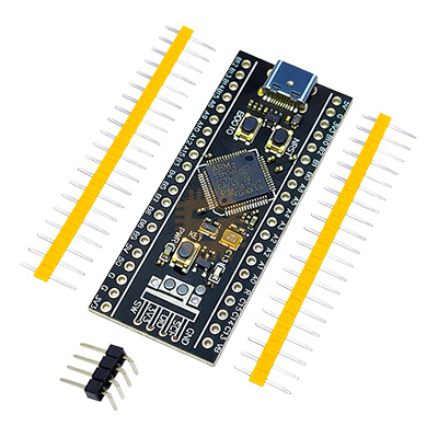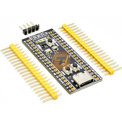
STM32F411CEU6 Development Board V3.0 256KB ROM
Price in Sri Lanka
ARM Dev BoardsDevelopment Boards and Programmers
Tronic.lk

Rs 1,300
In stock
Updated 01 Nov 2026
Opening hours
Open now
- Monday09:00 - 19:00
- Tuesday09:00 - 19:00
- Wednesday09:00 - 19:00
- Thursday09:00 - 19:00
- Friday09:00 - 19:00
- Saturday09:00 - 19:00
- SundayToday09:00 - 19:00
Search for it on
Description
The STM32F411CEU6 V3.0 Development Board (popularly known as the STM32F411 Black Pill) is a high-performance, budget-friendly ARM Cortex-M4 microcontroller board. Powered by STMicroelectronics' STM32F411CEU6 chip operating at up to 100 MHz with an integrated Floating Point Unit (FPU), this module offers a substantial step up in speed, RAM, and flash memory over standard 8-bit microcontrollers and older Cortex-M3 boards (like the STM32F103 "Blue Pill").
Specification
- Core Processor: ARM 32-bit Cortex-M4 CPU with FPU (Floating Point Unit)
- Maximum Clock Frequency: 100 MHz (via onboard 25 MHz high-speed crystal)
- Memory Architecture:
- On-Chip Flash Memory: 256 KB
- Internal SRAM: 128 KB
- Board Revision: V3.0 (Features refined PCB trace routing, stable power rails, and optional external SPI Flash pads on the underside)
- Peripherals & I/O Breakdown:
- Up to 36 usable GPIO pins (5V-tolerant on most I/O pins)
- 1x 12-bit, 2.4 MSPS Analog-to-Digital Converter (ADC) up to 16 channels
- Advanced Timers: 1x 16-bit motor control PWM, 5x general-purpose 16-bit, 2x 32-bit timers
- Digital Communication Interfaces: 3x USART/UART, 3x SPI (up to 50 Mbit/s), 3x I2C, 5x I2S
- Full-Speed USB 2.0 OTG Hardware Peripheral
- USB Socket Interface: Modern USB Type-C female connector
- Debugging / Programming Protocols:
- 4-Pin SWD (Serial Wire Debug) Header Pins
- Native USB DFU (Device Firmware Upgrade) Bootloader
- Operating Supply Voltages: 3.3V or 5.0V DC (Includes onboard 3.3V Low-Dropout Regulator)
- User Controls & LEDs:
- 1x Power Status LED (Red)
- 1x User Programmable LED (Blue, typically on pin
C13) - 2x Tactile Switches (
NRSTReset +KEYUser/Boot button)
Features
- High-Speed ARM Cortex-M4 Core with DSP & FPU: Capable of executing single-cycle DSP instructions and floating-point hardware arithmetic, making it ideal for real-time mathematical calculations, signal processing, and motor control algorithms.
- Modern USB Type-C Interface: Outfitted with a durable USB Type-C connector for board power, serial communication emulation, and direct USB DFU firmware flashing without requiring an external serial converter.
- Underside SOIC-8 Pad Array for External Flash Memory: The V3.0 board design includes dedicated mounting pads on the bottom PCB surface to solder an optional Winbond SPI Flash IC (e.g., W25Q32 or W25Q64), adding up to 8MB - 16MB of non-volatile file storage for logging, fonts, or assets.
- Breadboard-Friendly Form Factor: Features dual single-row 2.54mm header pins with standard pin spacing, making it easy to plug directly into solderless breadboards for quick prototyping.
Common Applications
- Flight Controllers & Drone Systems: Running complex attitude estimation, PID control loops, and sensor fusion algorithms (e.g., Betaflight / INAV targets).
- Advanced Audio Processing: Processing digital audio signals, synthesizing waveforms, or driving I2S digital-to-analog audio codecs in real time.
- Embedded Machine Learning & TinyML: Executing lightweight edge neural networks and sensor classification models locally using CMSIS-DSP libraries.
- USB Human Interface Devices (HID): Building custom macro pads, game controllers, USB keyboards, or high-speed data loggers.
Professional Programming & Usage Tips
- Use the Correct Programmer (ST-Link V2): The cleanest way to debug and program this board is with an external ST-Link V2 programmer connected to the 4-pin SWD header (
GND,3V3,SWCLK,SWDIO). - Flashing via Native USB DFU Bootloader:
- Hold down the BOOT0 / KEY switch.
- Press and release the NRST Reset switch.
- Release the BOOT0 switch.
- The board will enter the internal ROM DFU bootloader and appear as a USB device, allowing firmware uploads directly over a USB Type-C cable using tools like STM32CubeProgrammer or DFU-Util.
- Enable Arduino IDE Support: To program the Black Pill inside Arduino IDE, install the STM32 Cores by STMicroelectronics package via the Board Manager. Select
Generic STM32F4 series->Board part number: BlackPill F411CE. - Mind 3.3V Logic Level Constraints: While many GPIO pins on the STM32F411CEU6 are 5V-tolerant (marked with "FT" in the datasheet), analog pins (
ADC) and power rails operate strictly on 3.3V. Always verify pin tolerance before connecting 5V digital sensors to avoid damaging the internal MCU silicon.
Frequently asked questions
What is the price of STM32F411CEU6 Development Board V3.0 256KB ROM in Sri Lanka?▾
The current price of STM32F411CEU6 Development Board V3.0 256KB ROM in Sri Lanka is Rs 1,300 at Tronic.lk.
Is STM32F411CEU6 Development Board V3.0 256KB ROM available in Sri Lanka?▾
Yes, STM32F411CEU6 Development Board V3.0 256KB ROM is currently in stock at Tronic.lk in Sri Lanka.
Where can I buy STM32F411CEU6 Development Board V3.0 256KB ROM in Sri Lanka?▾
You can buy STM32F411CEU6 Development Board V3.0 256KB ROM in Sri Lanka at Tronic.lk. Visit 37left.lk to compare prices across multiple shops and find the best deal.
Loading...