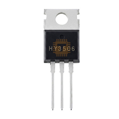
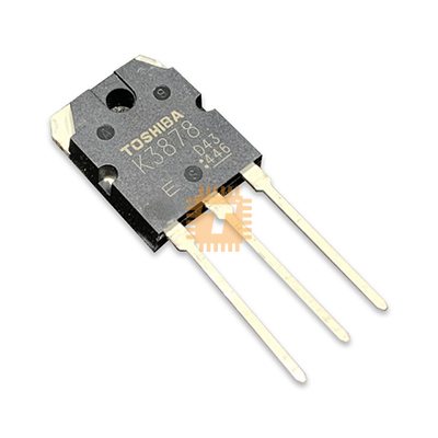
Original IRFP4110 N-Channel Power MOSFET TO-247
Price in Sri Lanka
FETTransistors and Diodes
Tronic.lk

Rs 490
In stock
Updated 01 Nov 2026
Opening hours
Closed now
- Monday09:00 - 19:00
- Tuesday09:00 - 19:00
- Wednesday09:00 - 19:00
- Thursday09:00 - 19:00
- Friday09:00 - 19:00
- Saturday09:00 - 19:00
- SundayToday09:00 - 19:00
Search for it on
Description
The IRFP4110 is an ultra-low on-resistance, high-current N-Channel HEXFET power MOSFET housed in a heavy-duty TO-247AC through-hole package. Utilizing advanced planar processing technology, the IRFP4110 is engineered to deliver extremely low on-state resistance (RDS(ON)), fast dynamic switching speeds, and high avalanche energy ruggedness. It is widely used in high-power electric vehicle (EV) motor controllers, solar inverters, high-current DC-DC converters, battery management systems (BMS), and uninterruptible power supplies (UPS).
Specifications
- Brand / Manufacturer: Infineon Technologies / International Rectifier (IR)
- Part Number: IRFP4110 / IRFP4110PBF
- Transistor Type: N-Channel Power MOSFET
- Drain-Source Breakdown Voltage (VDS): 100V
- Gate-Source Voltage (VGS): ±20V
- Continuous Drain Current (ID): 180A (at TC = 25°C, Silicon Limited) / 120A (Package Limited)
- Continuous Drain Current (ID): 130A (at TC = 100°C)
- Pulsed Drain Current (IDM): 670A
- Static Drain-Source On-Resistance (RDS(ON)): < 4>GS = 10V, ID = 75A)
- Gate Threshold Voltage (VGS(th)): 2.0V to 4.0V (Typical ~3.0V)
- Total Gate Charge (Qg): Approx. 150nC (at VGS = 10V, VDS = 50V)
- Single Pulse Avalanche Energy (EAS): Up to 190mJ (at IAS = 75A)
- Maximum Power Dissipation (PD): 370W (at TC = 25°C)
- Operating Junction & Storage Temperature Range: -55°C to +175°C
- Package / Case: TO-247AC (3-Pin Through-Hole: Pin 1: Gate, Pin 2: Drain, Pin 3: Source, Mounting Tab: Drain)
Features
- Ultra-Low On-Resistance (4.5mΩ Max): Drastically reduces conduction losses, minimizes I²R heat generation, and improves system efficiency in high-current switching applications.
- High Continuous Current Capacity: Capable of delivering up to 180A continuous drain current (120A package-limited) with peak pulse handling up to 670A.
- High Operating Junction Temperature (175°C): Provides exceptional thermal headroom and reliability in harsh, high-temperature industrial and automotive environments.
- High Avalanche Ruggedness: 100% avalanche tested to withstand inductive kickback energy spikes without avalanche breakdown failure.
- Heavy-Duty TO-247 Package: Large copper mounting tab enables superior thermal dissipation and direct bolt-on heatsink mounting for high-power thermal management.
Common Applications
- Electric Vehicle & E-Bike Motor Controllers: High-current primary switching in brushless DC (BLDC) motor drivers and synchronous PWM inverters.
- High-Power Pure Sine Wave Inverters: Primary bridge switching for 24V, 48V, and 72V DC-to-AC power inverters and solar converters.
- Battery Management Systems (BMS) & Solid-State Relays: High-current battery disconnect switches and power distribution units.
- High-Power DC-DC Buck/Boost Converters: Synchronous rectification and primary power switching stages in industrial power supplies.
- High-Power Spot Welders & Inductive Heaters: Extreme pulsed-current switching in DIY and industrial spot welding controllers.
Usage Tips
- Heatsink & Thermal Interface: Always mount the TO-247 package to an adequately sized aluminum heatsink using high-performance thermal paste (and an electrical insulator if the heatsink cannot be tied to Drain/V+).
- Dedicated Gate Driver IC: Due to the high gate charge (Qg ≈ 150nC), use a dedicated high-current MOSFET driver (such as IR2110, TC4420, or UCC27524) to ensure fast charging/discharging and prevent slow switching transitions that cause thermal runaway.
- Gate Series Resistor: Place a 4.7Ω to 15Ω resistor in series with the Gate (Pin 1) to eliminate parasitic high-frequency ringing without causing excessive switching delays.
- Gate-to-Source Pull-Down Resistor: Connect a 10kΩ resistor directly across Gate and Source (Pin 3) to keep the MOSFET solidly in the OFF state during circuit bootup or floating driver conditions.
Frequently asked questions
What is the price of Original IRFP4110 N-Channel Power MOSFET TO-247 in Sri Lanka?▾
The current price of Original IRFP4110 N-Channel Power MOSFET TO-247 in Sri Lanka is Rs 490 at Tronic.lk.
Is Original IRFP4110 N-Channel Power MOSFET TO-247 available in Sri Lanka?▾
Yes, Original IRFP4110 N-Channel Power MOSFET TO-247 is currently in stock at Tronic.lk in Sri Lanka.
Where can I buy Original IRFP4110 N-Channel Power MOSFET TO-247 in Sri Lanka?▾
You can buy Original IRFP4110 N-Channel Power MOSFET TO-247 in Sri Lanka at Tronic.lk. Visit 37left.lk to compare prices across multiple shops and find the best deal.
Loading...