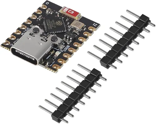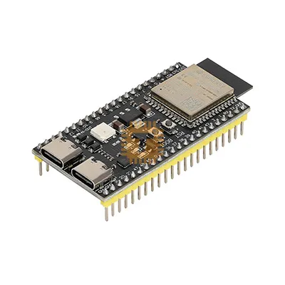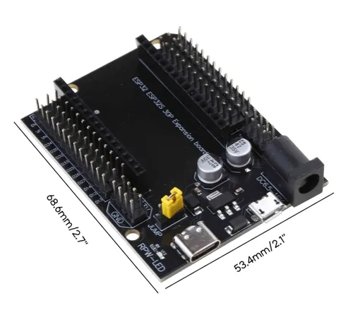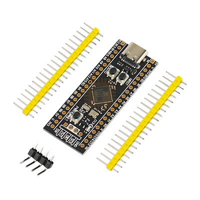
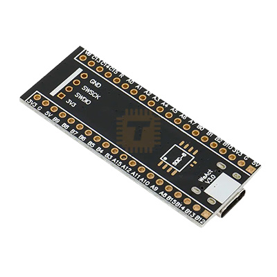
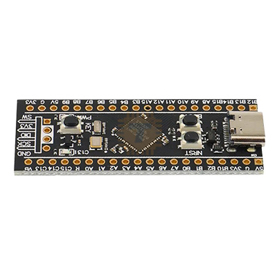
STM32F401CCU6 Development Board WeAct V3.0 Price in Sri Lanka

Tronic.lkListing · checkedChecked 10 Nov 2026
Rs1,070In stock
Go to Tronic.lk ↗https://tronic.lk/product/stm32f401ccu6-development-board-weact-v3-0Call0777854444WhatsApp+94764485607
Search for it on
Price history
Price at Tronic.lk at the end of each day · last 90 daysNo price history yetWe started tracking this listing recently. The chart and change tables appear after the first price or stock change.
Price insights
- Today at Tronic.lk
- Rs1,070
Description
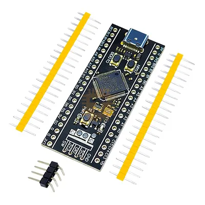
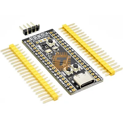
The STM32F401CCU6 Development Board WeAct V3.0 (commonly known as the WeAct "BlackPill") is a high-performance, compact 32-bit ARM Cortex-M4 development board engineered for embedded computing, robotics control, DSP processing, and real-time IoT prototyping. Powered by the STMicroelectronics STM32F401CCU6 microcontroller operating at up to 84 MHz, it integrates a hardware single-precision Floating Point Unit (FPU), digital signal processing (DSP) instructions, and 256 KB of high-speed embedded flash memory. Built with high-quality hardware upgrades in the WeAct V3.0 revision—including a USB Type-C interface, dual onboard crystal oscillators, dedicated boot/reset tactile switches, and an unpopulated SOIC-8 footprint for external SPI flash expansion—it serves as a low-cost, drop-in computing upgrade over traditional 8-bit boards and entry-level STM32F103 "BluePill" modules.
Specifications
- Board Model / Revision: WeAct Studio STM32F401 Core Board (Version 3.0 / BlackPill)
- Primary Microcontroller: STMicroelectronics STM32F401CCU6
- Processor Architecture: 32-bit ARM Cortex-M4 with Hardware FPU (Single-Precision) & DSP Instruction Set
- Maximum CPU Core Clock Frequency: 84 MHz
- Embedded Flash Memory: 256 KB
- Internal SRAM: 64 KB
- External Memory Expansion: Onboard unpopulated SOIC-8 pad for SPI NOR Flash (supports W25Q32, W25Q64, W25Q128)
- Operating Logic Voltage: 3.3 V DC
- Input Voltage Limits:
- Via USB Type-C: 5.0 V DC (Regulated down via onboard ultra-low-dropout 3.3V LDO)
- Via 5V Pin: 4.8 V to 5.5 V DC
- Via 3V3 Pin: 3.0 V to 3.6 V DC (Direct regulated input)
- I/O & Peripherals:
- Total General Purpose I/O (GPIO): Up to 36 accessible pins (Most are 5V-tolerant)
- Analog-to-Digital Converter (ADC): 1 × 12-bit SAR ADC (Up to 16 external channels / 2.4 MSPS)
- Timers: Up to 11 timers (Advanced control, 16-bit, and 32-bit general-purpose PWM timers)
- Communication Interfaces: 3 × USART/UART, 3 × I2C, 4 × SPI (with multiplexed I2S for high-end audio)
- USB OTG: 1 × USB 2.0 Full-Speed On-The-Go (FS OTG 12 Mbps) interface supported natively by hardware
- Crystals & Clock Sources:
- High-Speed External (HSE): 25 MHz High-Precision Passive Quartz Crystal
- Low-Speed External (LSE): 32.768 kHz RTC Quartz Crystal (for internal real-time clock calibration)
- User Interface & Controls:
- Tactile Switches: Reset Button (NRST), Boot Mode Selector (BOOT0), and User Programmable Key (KEY / PA0)
- LED Indicators: 1 × Power LED (PWR - Red), 1 × User Status LED (LED - Blue, connected to PC13)
- Debug & Programming Interface:
- Standard 4-Pin SWD Header (3V3, SWDIO/PA13, SWCLK/PA14, GND) for ST-Link / J-Link / DAPLink
- Native USB DFU Bootloader support via BOOT0 button
- Form Factor & Pin Pitch: Dual-in-Line 40-Pin DIP layout with standard 2.54 mm (0.1") pitch (Breadboard compatible)
- PCB Dimensions: Approx. 53.0 mm × 20.8 mm (L × W)
- Net Weight: Approx. 6.0 g (without headers soldered)
Features
- Hardware FPU & DSP Math Acceleration: Cortex-M4 core computes floating-point math, trigonometric calculations, PID loops, and digital filtering in single clock cycles, vastly outperforming Cortex-M3 (F103) devices.
- Modern USB Type-C Connector: Features a durable USB-C receptacle for firmware flashing, virtual COM port telemetry, and power input, complete with CC pull-down resistors for seamless compatibility with C-to-C cables.
- Dual Factory Oscillators: Includes a 25 MHz main oscillator for accurate USB bus clock generation (48 MHz PLL branch) and a 32.768 kHz RTC crystal for precise timekeeping in low-power sleep modes.
- Built-in DFU ROM Bootloader: Easily flashed via standard USB-C cable without needing an external programmer by holding BOOT0 on power-up.
- Unpopulated SPI Flash Footprint: Solder pads on the underside of the PCB allow adding an external 4MB–16MB SPI flash IC for storing MicroPython scripts, font libraries, audio waveforms, or sensor logs.
- Wide Software Ecosystem: Supported by STM32CubeIDE, Keil MDK, PlatformIO, Arduino IDE (via STM32duino core), MicroPython, and CircuitPython.
Common Applications
- Robotics & Flight Controllers: Multi-axis drone flight stabilization, inverse kinematics for hexapods/robotic arms, and high-frequency brushless motor field-oriented control (FOC).
- Custom USB Human Interface Devices (HID): Building custom mechanical keyboards, macro pads, flight simulator rudder pedals, and low-latency gaming peripherals.
- Digital Audio Synthesizers & DSP Filters: Real-time I2S audio decoding, wave synthesis, graphic equalizer processing, and acoustic spectrum analyzers.
- Data Acquisition & High-Speed Telemetry: High-sample-rate oscilloscope probes, logic analyzers, vibration analysis nodes, and CAN bus industrial gateways.
- Smart IoT & Wearable Nodes: Compact edge computing devices executing local machine learning inferencing (TinyML) and sensor fusion algorithms.
Usage Tips
- Flashing via Native USB (DFU Mode):
- You do not need an external ST-Link programmer to upload code. Hold down the BOOT0 button, tap the NRST (Reset) button once, and release BOOT0 to drop the chip into the internal ST factory DFU bootloader.
- Upload binary or hex files directly using STM32CubeProgrammer, dfu-util, or the Arduino IDE / PlatformIO upload utility set to "DFU" mode.
- Arduino IDE Configuration (STM32duino):
- Install the "STM32 MCU Based Boards" package via the Arduino Boards Manager.
- Under the Tools menu, set:
- Board: "Generic STM32F4 series"
- Board part number: "BlackPill F401CC"
- U(S)ART support: "Enabled (generic 'Serial')"
- USB support (if using serial prints over USB): "CDC (generic 'Serial' supersede U(S)ART)"
- Upload method: "STM32CubeProgrammer (DFU)" or "SWD" (if using ST-Link)
- SWD Debug Header Wiring:
- When using an external ST-Link V2 programmer, connect the 4-pin SWD header located at the tail end: 3V3 → 3.3V, GND → GND, SWDIO → SWDIO, SWCLK → SWCLK.
- Do NOT power the board through both the USB Type-C port and the ST-Link 3.3V/5V pins simultaneously, as this can back-feed current into your computer's USB controller and damage the LDO regulator.
- 5V Tolerance Considerations:
- While the majority of STM32F401 GPIO pins are 5V-tolerant (marked "FT" in the datasheet), pins configured in analog mode (ADC inputs) or true open-drain without clamping are limited strictly to 3.6V max.
- Always double-check the pin table before connecting 5V TTL sensors to analog ADC pins (PA0–PA7, PB0–PB1).
- Breadboard Soldering Alignment: Insert the included 20-pin dual male header strips into a solderless breadboard first, set the PCB on top, and solder the pins while seated. This ensures the pins stay perpendicular and line up with breadboard sockets.
Questions
About this listing at Tronic.lkWhat is the price of STM32F401CCU6 Development Board WeAct V3.0 at Tronic.lk in Sri Lanka?
Rs 1,070, checked 10 Nov 2026.
Is STM32F401CCU6 Development Board WeAct V3.0 in stock at Tronic.lk in Sri Lanka?
Yes, it was in stock at Tronic.lk at the last check.
Where can I buy STM32F401CCU6 Development Board WeAct V3.0 in Sri Lanka?
Tronic.lk sells it on tronic.lk. You can also call or WhatsApp the shop during opening hours.
Rs1,070at Tronic.lk · In stock
Go to Tronic.lk ↗https://tronic.lk/product/stm32f401ccu6-development-board-weact-v3-0