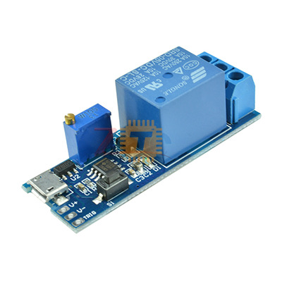
Adjustable Delay Timer Switch 5-30V MicroUSB
Price in Sri Lanka
Available at 1 shop
From Rs 480
Compare prices

Price history
Tronic.lk · Power
Description
The Adjustable Delay Timer Module is a versatile trigger-delay switch that uses a 555-based timing circuit to control a high-power relay. It features dual power input options (screw terminals or MicroUSB) and is designed for high stability in industrial environments. Once triggered by a button press or an external pulse, the relay activates for a set duration (0-24 seconds) before automatically switching off.
Specifications
- Operating Voltage: Wide voltage DC 5V to 30V
- Power Interfaces: 2-pin Screw Terminal or MicroUSB (5V)
- Trigger Signal: High Level (3.0V to 24V) or built-in trigger button
- Output Capacity:
- AC: 250V / 10A
- DC: 30V / 10A
- Delay Time: Default 0 to 24 seconds (Adjustable)
- Timing Formula: T = 1.1 * R * C
Operating Mode
- Initial State: The relay is "Off." The Common (COM) terminal is connected to the Normally Closed (NC) terminal, and the Normally Open (NO) terminal is disconnected.
- Triggered State: When a high pulse signal is provided or the trigger button is pressed, the relay activates and the indicator light turns on. The COM terminal connects to the NO terminal.
- Delay Sequence: The relay stays "On" for the duration set by the potentiometer.
- Reset: After the time elapses (0-24s), the relay automatically switches off and returns to the initial state, waiting for the next trigger.
Features
- Dual Power Input: Can be powered easily via a standard 5V MicroUSB phone charger or a DC power supply (up to 30V).
- High Anti-Interference: The trigger input is designed with a pull-up and filter circuit, making it stable in electromagnetic environments or during power-up/down moments.
- Adjustable Timing: The delay length is adjusted via an onboard multi-turn potentiometer. For longer delays, the C2 capacitor or the potentiometer can be replaced with higher values.
- Passive Relay Contacts: The relay acts as a simple switch (dry contacts) and does not output electricity itself, allowing it to control different voltage circuits than the one powering the module.
- Freewheeling Protection: Includes an onboard diode to protect the circuit from inductive voltage spikes when the relay coil de-energizes.
Pin and Terminal Guide
- Input Side:
- V+ / V-: DC Power Input (5V to 30V).
- MicroUSB: 5V Power Input.
- Trig: External trigger signal input.
- Output Side (Relay):
- NO (Normally Open): Connected to COM only when triggered.
- COM (Common): The shared terminal for the load.
- NC (Normally Closed): Connected to COM by default when the timer is idle.
Common Applications
- Anti-Theft Alarms: Delaying the activation of a siren or light after a sensor is tripped.
- Equipment Protection: Delaying the start of heavy machinery to prevent power surges.
- Automotive Electronics: Keeping cabin lights or accessories on for a short period after the ignition is turned off.
- Smart Home: Controlling the "On" time for exhaust fans, pumps, or magnetic door locks.
Usage Tips
- Time Extension: To increase the delay beyond 24 seconds, you can solder a larger capacitor in place of C2. For example, a 220uF capacitor would increase the max delay to approximately 242 seconds.
- Trigger Isolation: The signal ground and system ground are separate to increase anti-interference, but they can be short-circuited together if a common ground is required for your specific trigger source.
- Passive Switching: Remember that the relay terminals act as a switch, not a power source. You must wire your load's power supply in series with the COM and NO terminals.
Frequently asked questions
What is the price of Adjustable Delay Timer Switch 5-30V MicroUSB in Sri Lanka?▾
The price of Adjustable Delay Timer Switch 5-30V MicroUSB in Sri Lanka is Rs 480 at 1 shop.
Where can I compare Adjustable Delay Timer Switch 5-30V MicroUSB prices in Sri Lanka?▾
37left.lk lists Adjustable Delay Timer Switch 5-30V MicroUSB prices from 1 shop in Sri Lanka on one page.
Is Adjustable Delay Timer Switch 5-30V MicroUSB available in Sri Lanka?▾
Yes, Adjustable Delay Timer Switch 5-30V MicroUSB is available in Sri Lanka at 1 shop.
Loading...